Legacy Screen Applications
Working with Mainframe (3270) and AS400 (5250) Green Screen Connectors
Overview
The OL Hub screen modules enable users to:
- communicate with mainframe or AS400 screen-based applications
- analyze screen recordings and define mainframe or AS400 screen assets from the OL Hub
Runtime Prerequisites
- The user must supply a terminal emulator for Mainframe (H3270) or AS400 (TN5250). The terminal emulator must be in the Java archive (.jar) format.
- The terminal emulator .jar file must be placed under Maven’s M2 repository or directly under the project’s classpath.
Designtime Prerequisites
- To run the terminal emulation from the CLI, the terminal emulator .jar file must be placed in the
Users/*<User>*.ol/cli/extra-classpath-resourcesdirectory. You must create the directory if it does not exist.
Note: Currently, the terminal emulation must be run from the CLI only.
Screen Modules
A screen module consists of:
- Connection details to the backend
- Screen Assets. Each screen asset consists of:
- Identifiers - A set of visual definitions that uniquely identify a screen. For example:
- a specific text on a certain position on the screen
- a position on the screen being editable or not
- a specific color at a certain position on the screen
- Fields - consisting of all displayable areas on the screen
- Tables - consisting of
- Rows and Columns
- Actions. There are two types of Actions:
- Table Actions - Actions that affect the entire table, such as page up, page down
- Table Row Actions - Actions that affect a specific table record
- Identifiers - A set of visual definitions that uniquely identify a screen. For example:
Operational Flow
- Create a screen module in the CLI with a connector type appropriate to the backend.
- Create the connection profile for the module by running the ol test connection command with the required options.
- To be able to run the screen analysis and editing in the OL Hub, push the screen module to the OL Hub.
- Run the ol start emulation CLI command to invoke the mainframe or AS400 emulation.
- In the web browser that opens, login to the backend with the backend user's credentials.
- Proceed as desired in the backend session.
- When finished with the backend session, logoff from the backend.
- The session recording is saved in the Trail file.
- Upload the Trail file to the OL Hub module.
- Review and accept/edit the suggestions for screen asset names.
- Edit the screen assets as desired.
Screen Projects
More than one screen module can be associated with the same project, allowing users to keep common screens—such as welcome and login screens—in a separate module that can be reused across multiple projects. This eliminates the need to redefine the same screens repeatedly. However, a project cannot be associated with both Screen and RPC modules at the same time.
The screen flow differs from the RPC flow:
- Define Inputs / Outputs.
- Drag screens to the Canvas.
- Connect the screens.
- Define Actions.
- Map input data to the screen
- Define emulation key press (Enter, F1, F2, etc.)
- Define output Mappings.
- Map data from the screen to the output.
Create a Screen Module in the OL Hub UI
-
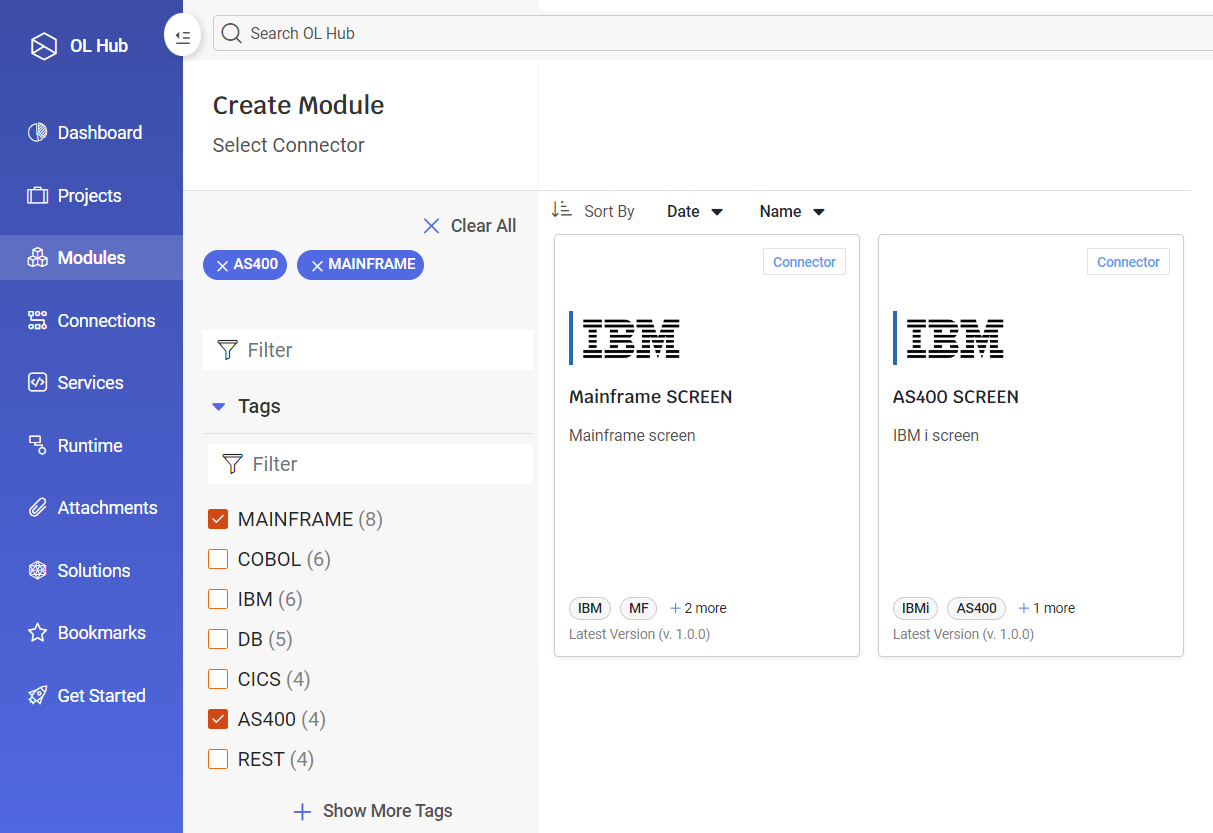
On the Modules page, click on + Create Module.

-
The Select Connector page is displayed. Select the desired Connector: MAINFRAME or AS400, then select the corresponding Screens connector: Mainframe SCREEN or AS400 SCREEN.
-
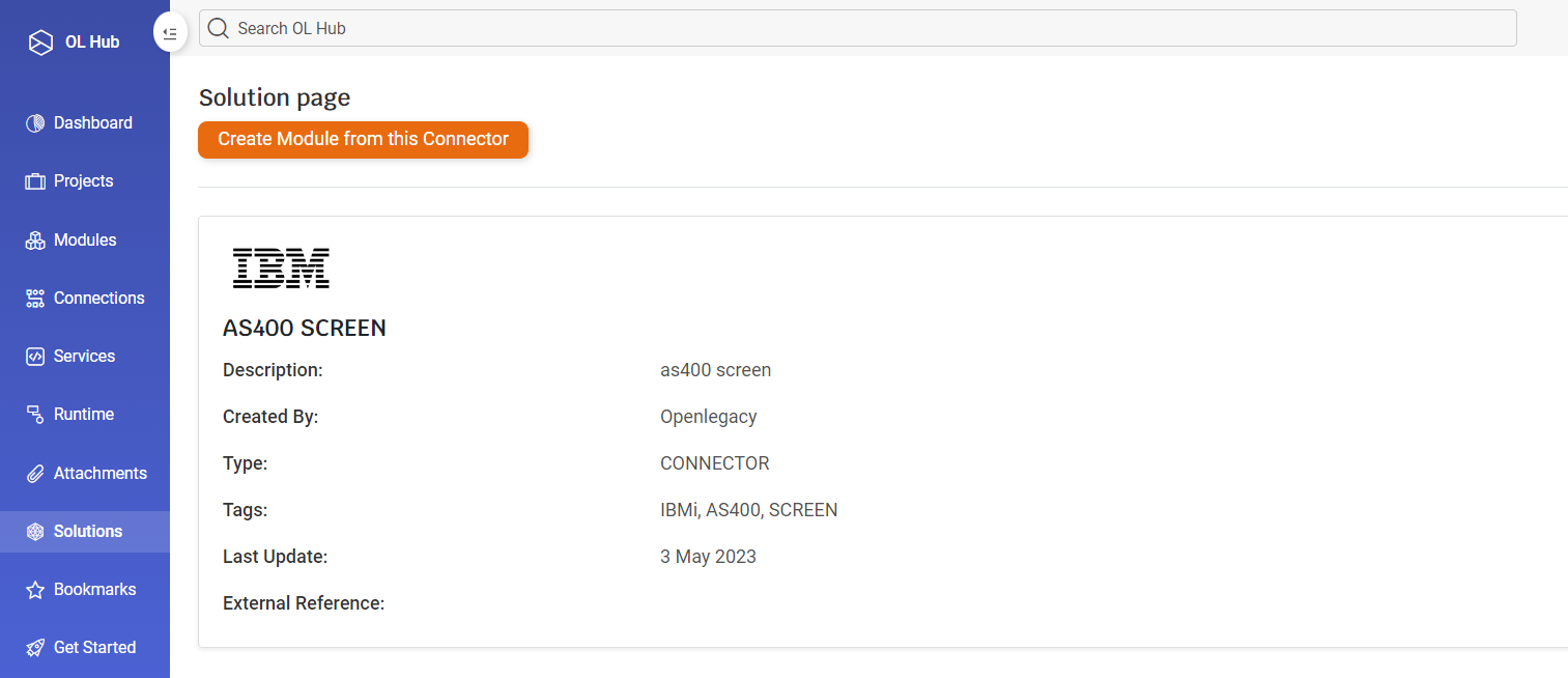
The Solution page is displayed. Click on Create Module from this Connector.
-
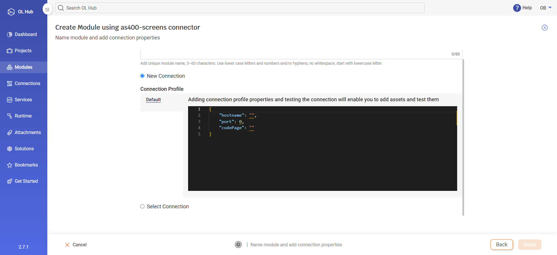
The Create Module using ...-screens connector page is displayed. Type a module name, select a new or existing connection, enter the required connection profile parameters and click Done.
Note: Currently, the terminal emulation must be run from the CLI only. However, you may upload emulation trail files to a screen module created in the OL Hub UI.
Create a Screen Module in the CLI
- Create a screen module in the CLI using the ol create module command. For example:
>ol create module as400-screens-module --connector as400-screens$ol create module as400-screens-module --connector as400-screens - The Connection profile is stored in the file module.json. Create the default profile by running the ol test connection command from the module folder with the required options:
as400-screens-module>ol test connection --host-name as400.openlegacy.com --port 23 --code-page CP037as400-screens-module$ol test connection --host-name as400.openlegacy.com --port 23 --code-page CP037 - Push the module to the OL Hub. This will enable subsequent analysis and editing of screen assets in the OL Hub.
>ol push module as400-screens-module$ol push module as400-screens-module
Run Backend Screen Emulation
-
Navigate to the screen module directory.
-
Run the emulation from the CLI:
as400-screens-module>ol start emulationas400-screens-module$ol start emulation -
The CLI output display begins by displaying the Spring Boot logo:
C:\OL Hub\as400-screens-module>ol start emulation [-] . ____ _ __ _ _ /\\ / ___'_ __ _ _(_)_ __ __ _ \ \ \ \ ( ( )\___ | '_ | '_| | '_ \/ _` | \ \ \ \ \\/ ___)| |_)| | | | | || (_| | ) ) ) ) ' |____| .__|_| |_|_| |_\__, | / / / / =========|_|==============|___/=/_/_/_/ :: Spring Boot :: (v3.1.6) ... [-] -
The emulator opens an emulation screen session in the user's default web browser:
-
Example 1: AS400
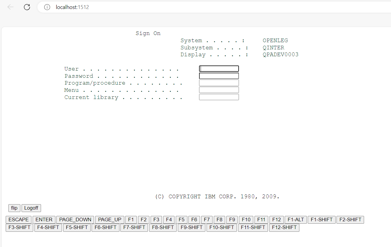
-
Example 2: Mainframe
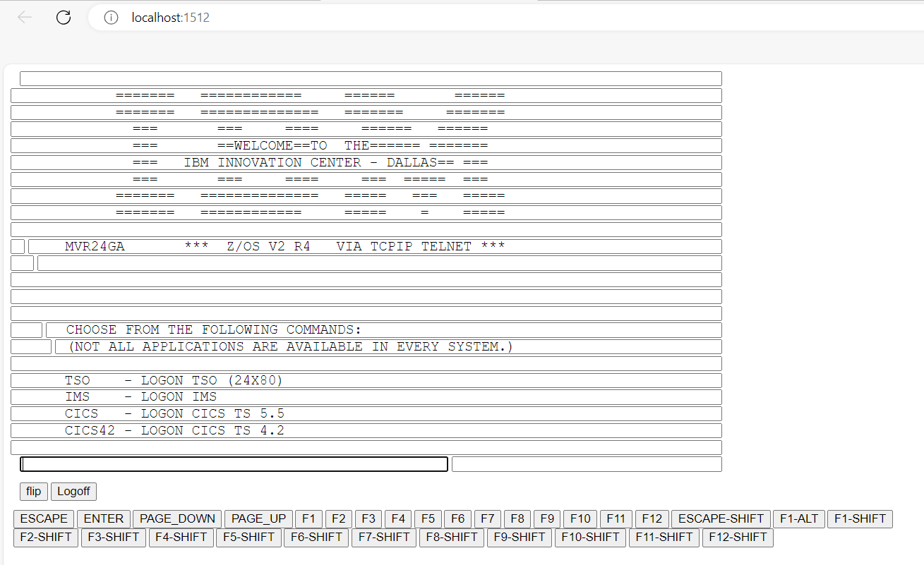
-
-
Navigate the screen application to record screens of interest. You can use the keyboard or the on-screen action keys. Click on the Enter button on the emulation screen or press the Enter key on the keyboard.
-
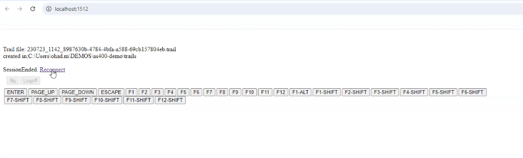
When finished with the session, press the Logoff button. A Trail file is created in the trails folder of the module directory. The Trail file contains a record of all the session transactions.
Uploading Trail Files to a Module in the OL Hub UI
-
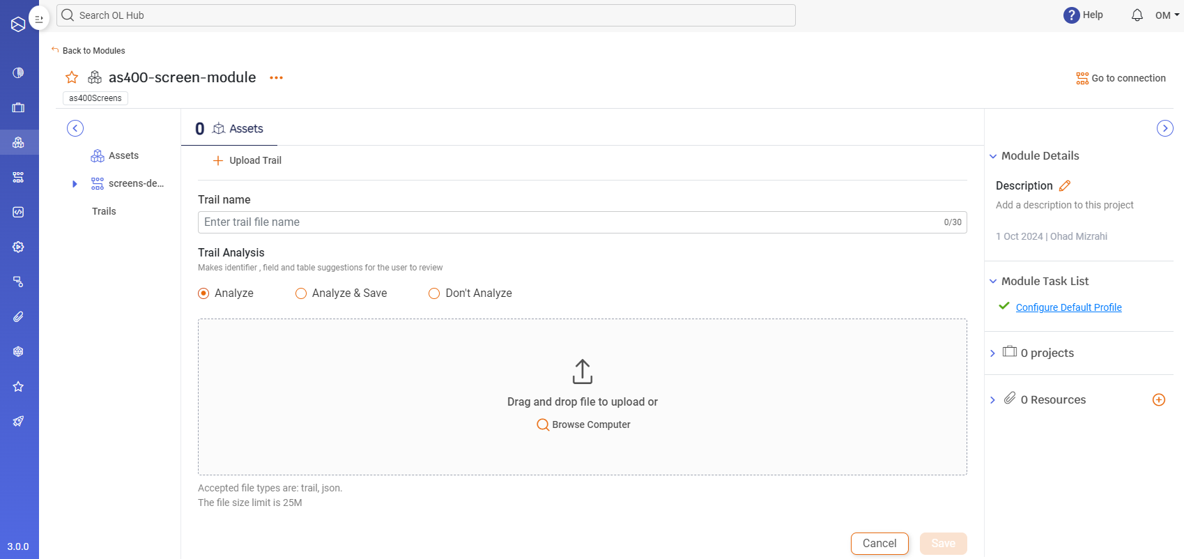
On the Modules page, select the module and then Click on + Analyze Trail.
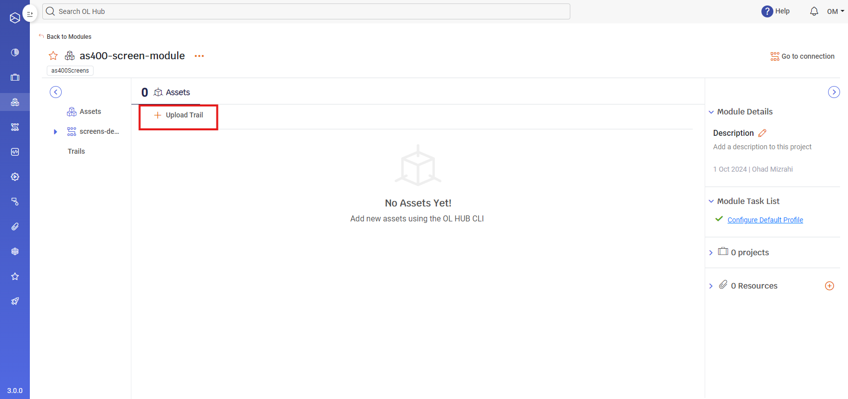
-
The select trail file page is displayed.
-
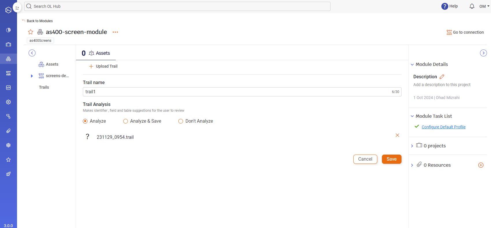
Enter a name for the uploaded trail file and drag and drop the file or browse the computer to upload the file.
-
Trail Analysis
-
Analyze: Analyzes the uploaded trail file and suggests screen names, screen identifiers, fields, and screen tables for each screen in the trail. Users should review and edit these suggestions before saving the screen assets.
-
Analyze & Save: Performs the same actions as the Analyze option, but automatically saves the suggested screen assets. If this option is selected, all screen assets will be saved without further review. This option should be used only when users have a high level of confidence in the analysis results, typically after manually reviewing previously generated screen assets.
-
Don’t Analyze: No automatic analysis is performed. Users will need to define all screen assets manually.
-
-
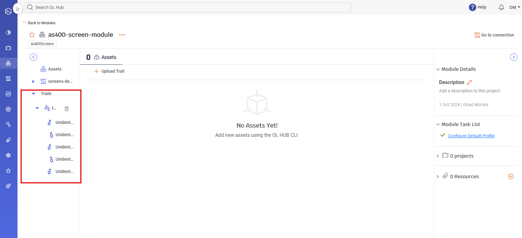
Click the Save button. The uploaded Trail file appears under the Trails section:
Adding Screen Assets
After uploading a Trail file, you are ready to define Screen Assets.
Defining Screen Assets includes:
- Naming the Screen Asset
- Configuring:
- Identifiers
- Fields
- Tables and Table Actions
-
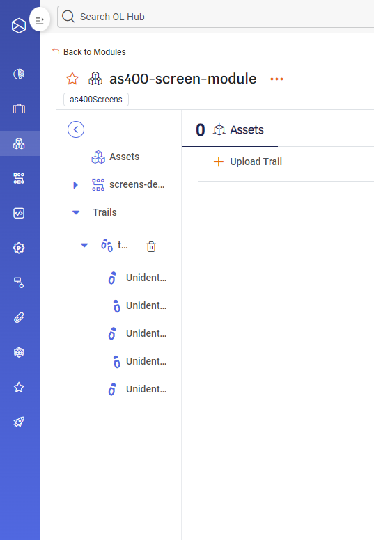
Expand the tab for the uploaded Trail file. Each entry for the Trail file represents a screen. Note that in the example below, all the screens are named Unidentified. This is because the Analyze checkbox was checked when the Trail file was uploaded.
-
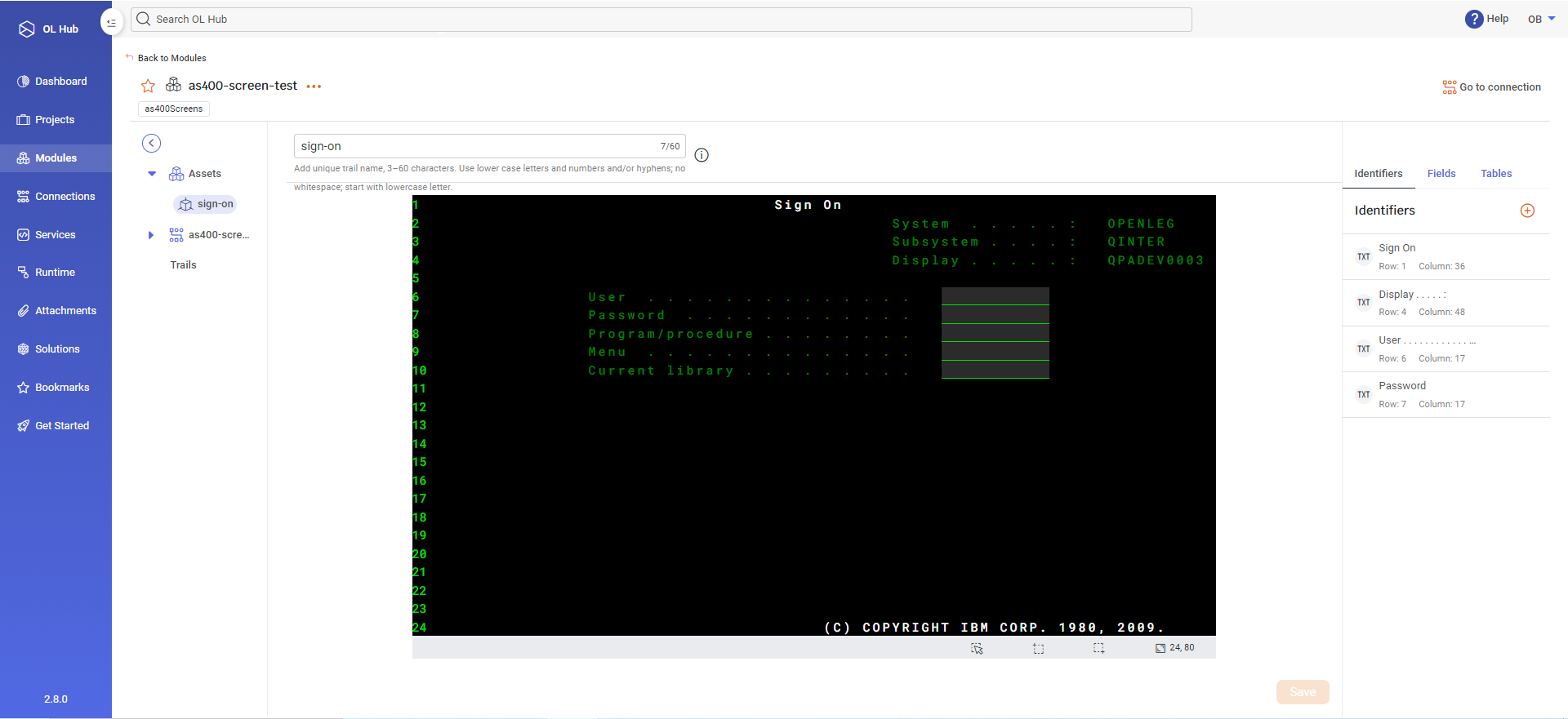
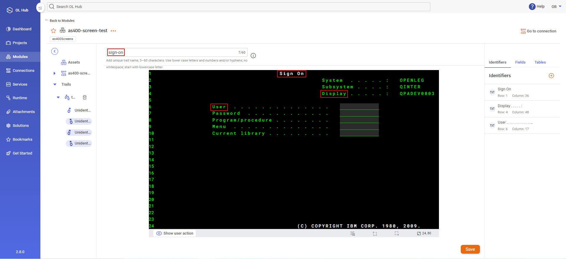
Click on a Trail file entry, in this example, marked as Unidentified. The screen captured by the emulator is displayed:
-
The Open Legacy Trail Analysis software presents suggestions for defining the Screen Asset:
- The suggested Screen Asset name is displayed in the trail name field. In this example, the name "sign-on" is suggested from the screen header "Sign On".
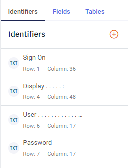
- Screen Assets are described by a set of Identifiers that the user defines. In the example above, the suggested Identifiers are displayed in the right-hand pane of the page. If all the Identifiers listed below are detected in the screen from the Trail file, then the Screen Asset name is identified during runtime as sign-on.
- The text Sign On beginning at Row 1, Column 36 of the screen
- The text Display beginning at Row 4, Column 48 of the screen
- The text User beginning at Row 6, Column 17 of the screen
-
You may change the Screen Asset name by editing the trail file name.
Configuring Identifiers
-
You may accept/modify/delete any of the suggested Identifiers and/or add additional Identifiers.
-
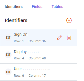
To modify or delete an Identifier, move the pointer to hover over the Identifier in the right-hand pane:
-
To delete the Identifier, click on the delete icon
 .
. -
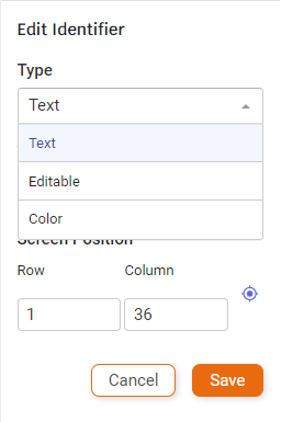
To edit the Identifier, click on the edit icon
 .
.
-
Select the Type of Identifier:
- Text - the Identifier will be recognized by the text specified in the Value field
- Editable - the Identifier will be editable/not editable when the Value field is selected as True/False
- Color - the Identifier will be recognized by the color selected in the Value field
-
Enter the Screen Position of the Identifier by specifying the Row and Column. You can use the row, column indicator at the bottom of the screen for assistance. In the example below, the pointer is on the letter "U" of User and the row, column indicator displays "6, 17".

-
-
To add an Identifier, move the cursor to the beginning of the new Identifier and click on the add icon
 to the right of Identifiers.
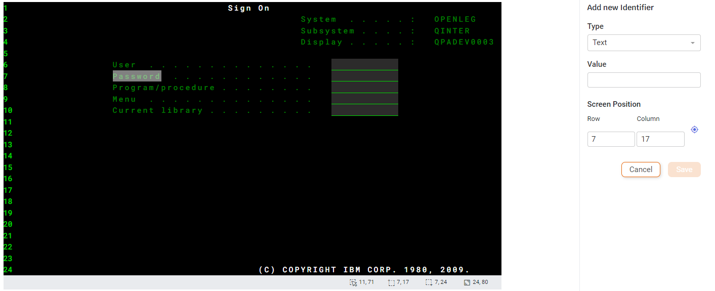
-
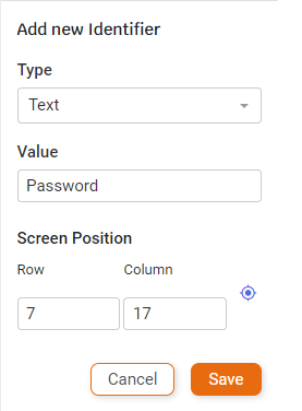
Enter the Type and Value. The Screen Position coordinates are automatically entered based on the cursor position in the screen. For example:
-
Click Save. The new Identifier appears in the list.

-
-
Configuring Fields
-
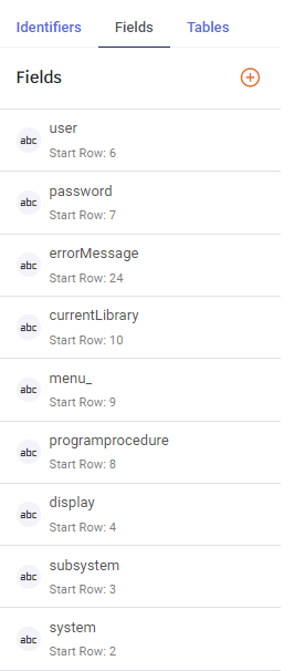
You may accept/modify/delete any of the suggested Fields and/or add additional Fields. For example:

-
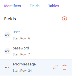
To modify or delete a Field, move the pointer to hover over the Field in the right-hand pane:
-
To delete the Field, click on the delete icon
. -
To edit the Field, click on the edit icon
.
-
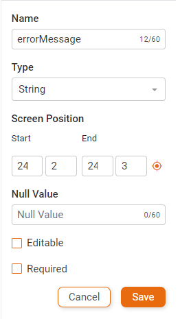
To change the Field Name, type a new name (up to 60 characters).
-
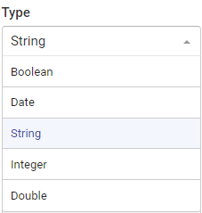
Select the Field Type from the available list.
-
Enter the Screen Position coordinates of the Field starting row, column and ending row, column.
-
Check/uncheck the Editable checkbox if the Field can/cannot be modified.
-
Check/uncheck the Required checkbox if the Field is/isn't required.
-
Depending on the Field Type selected, the remaining fields may be different:
-
For any Type except Boolean, you may enter a Null Value.
-
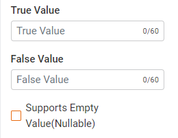
For Boolean Type, you may enter the True Value and False Value. You may check/uncheck the Supports Empty Value(Nullable) checkbox.
-
For Date Type, select either Pattern or Date columns positions, and enter the pattern or date column positions.

-
For Integer or Double Type, enter the Pattern.
-
After making all desired changes, click the Save button in the right-hand pane to save the changes to the Field.
-
-
-
To add a Field, move the cursor over the new Field and click on the add icon
to the right of Fields. Continue as described in step iii above for editing a Field.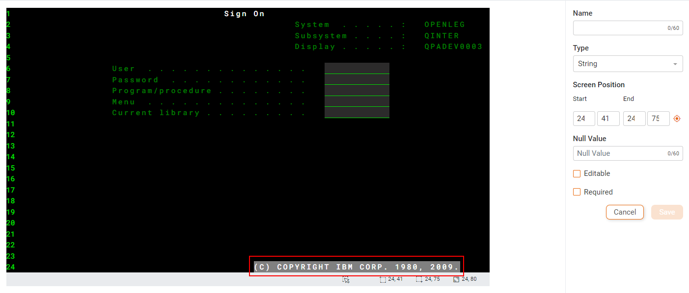
-
Configuring Tables
-
You may accept/modify/delete any of the suggested Tables and/or add additional Tables. For example:
-
To modify or delete a Table, move the pointer to hover over the Table in the right-hand pane:
-
To delete the Table, click on the delete icon
. -
To configure the Table, click on the
 icon to the right of the Table name. The following menu is displayed:
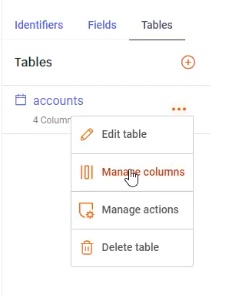
-
To edit the Table, click on Edit table.
-
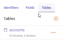
To edit the table columns, click on Manage columns.

-
To edit a column, click on the
icon to the right of the Column name. -
To add a column, click on the add icon
to the right of Columns.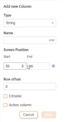
- Select the Column Type.
- Enter the Column Name.
- Enter the Screen Position Start and End columns.
- Enter the Row offset. This is the number of Row Gaps in the Table.
- Check/uncheck Editable if the Column is/isn't editable.
- Check/uncheck Action column if this Column is/isn't an action column.
- Click the Save button in the right-hand pane to save the new Column.
-
-
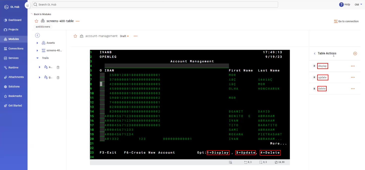
To edit the Table actions, click on Manage actions. The list of Table Actions is displayed. In the example below, there are 3 Table Actions defined, each corresponding to an option highlighted at the bottom of the screen. These actions are more correctly known as Table Row Actions because they are invoked for a specific Table row.
-
To add an action, click on the add icon
to the right of Table Actions.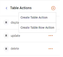
- Create Table Action adds an action that applies to the entire table. Examples are PageDown or PageUp.
- Create Table Row Action adds an action that applies to one row of the table, as in the example above: Display, Update or Delete.
-
-
-
To add a Table, drag the cursor over the desired rows of the Table, then click on the add icon
to the right of Tables.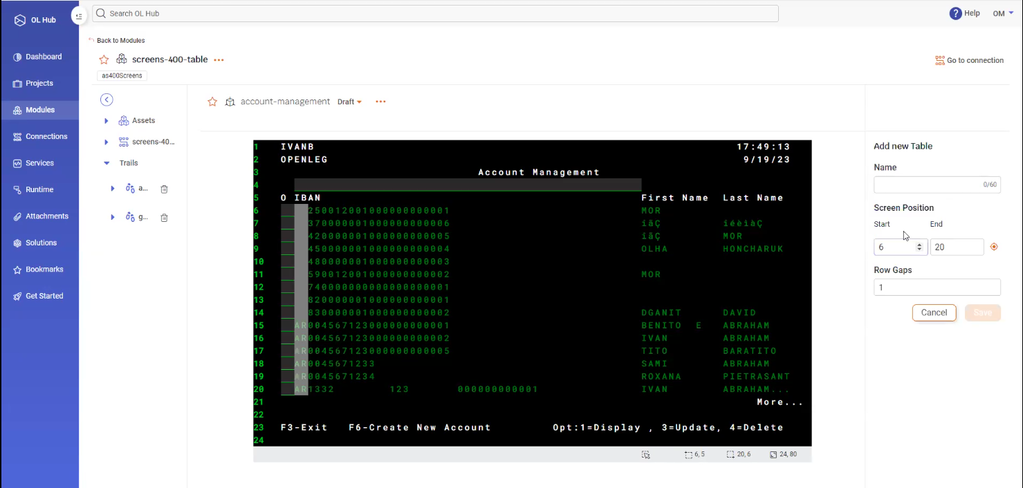
- Enter a Name for the Table.
- The Screen Position Start and End rows are automatically entered, corresponding to the rows marked by dragging the cursor.
- Enter the number of Row Gaps. This is the number of adjacent rows on the screen corresponding to one record in the Table.
- Click the Save button in the right-hand pane to save the new Table.
-
Saving the Screen Asset
-
After entering the trail name and verifying all Identifiers, Fields and Tables, click the Save button at the bottom right of the page.
-
The module now contains the saved Screen Asset.